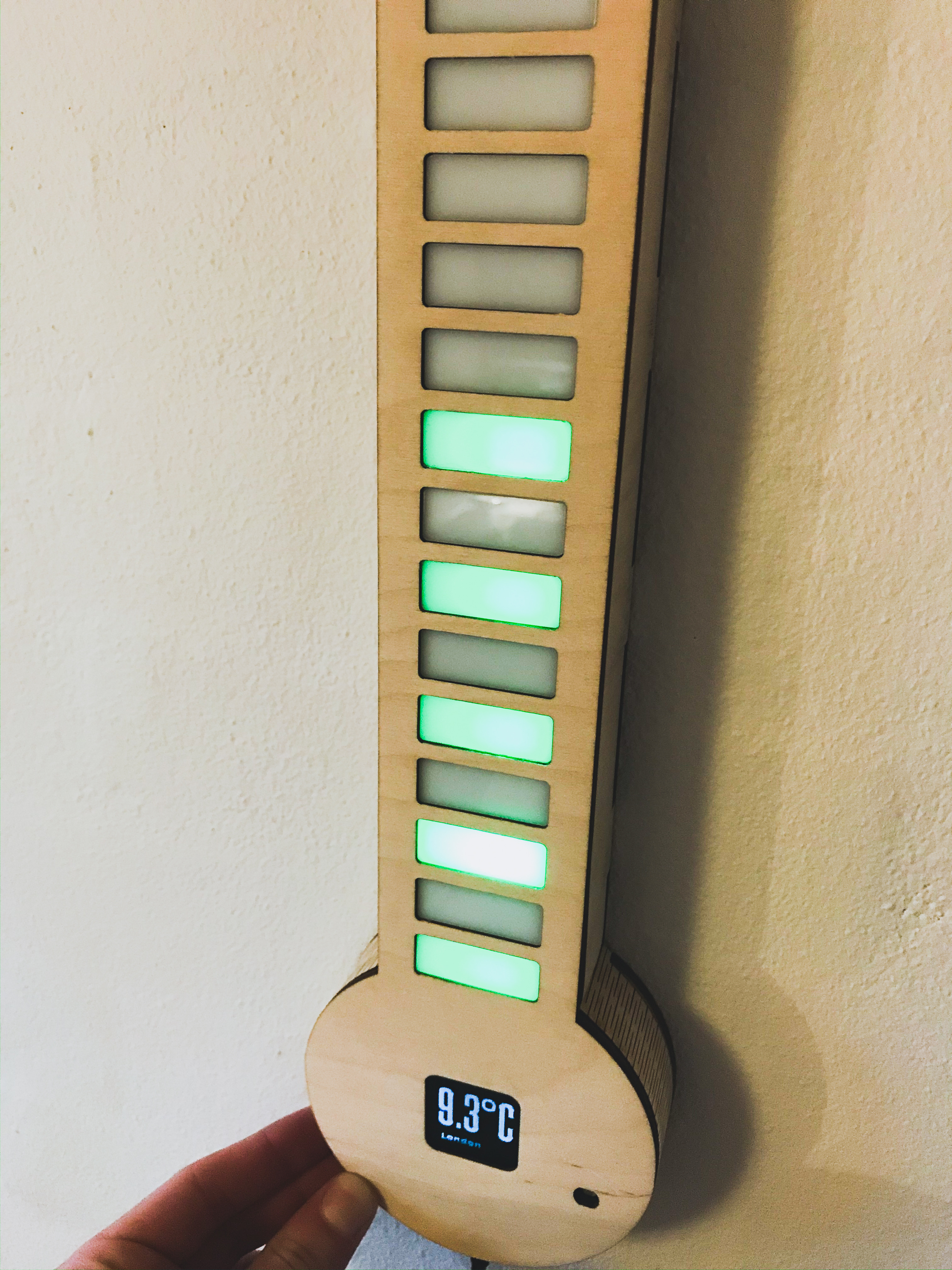
Check the outside temperature with a Raspberry Pi Zero W, LED strip and an Oled Display
Introduction
Learn how i made this Digital LED Thermometer, with a Raspberry Pi Zero W, LED strip, an OLED Display, and more.
It automatically cycles thought a list of cities, and displays the temperature on the Oled display, and with the LED's. But you can also manually select a city to display, using the buttons on the side.
On top of that, it will shut off the LED's and the Oled, if it's been inactive for a few minutes, and will turn back on, if it detects a significant light change (Controlled by an LDR).
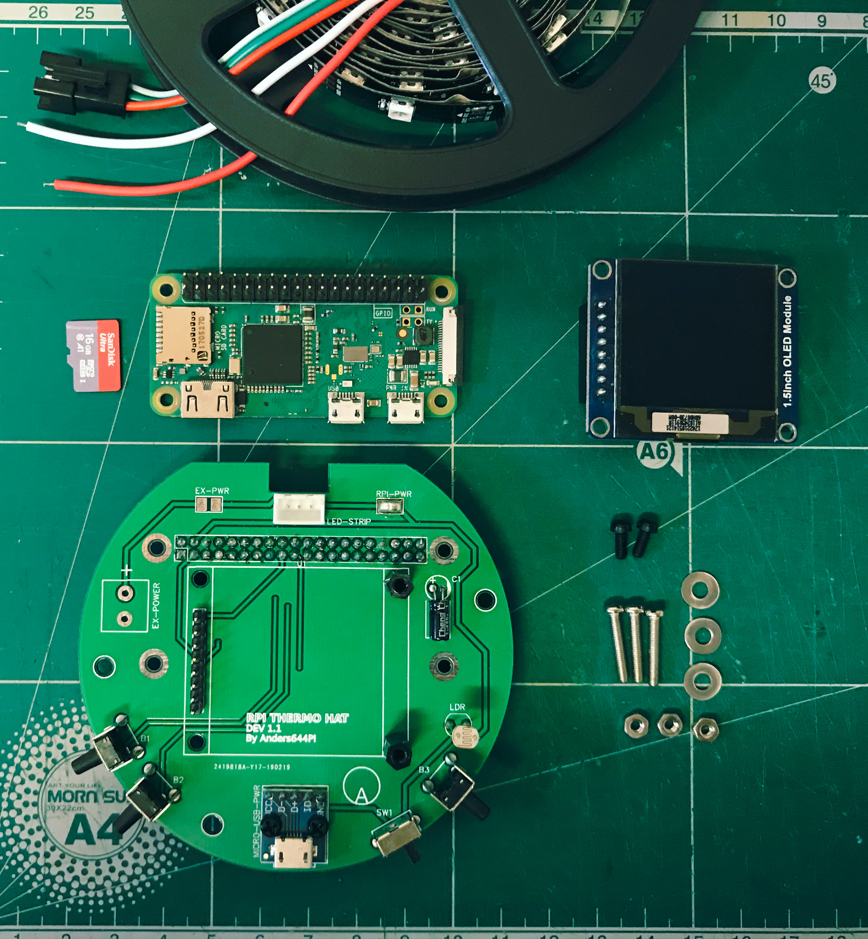
Components:
- A 1.5 Inch OLED Module by Waveshare
- A 5V 2.4A Power Supply for Raspberry Pi
- A 5m WS2812B LED Strip, 30 LEDs/m
- Screws, washers, bolts and standoffs.
- A Custom PCB, with buttons, a switch, an ldr, pin-headers, and more
- Soldering iron and solder
- Hot glue
- Wood glue
- 4mm and 6mm plywood
- 3mm white acrylic
Weather data
Credit to StuffWithKirby for his code on reading JSON weather data in python.
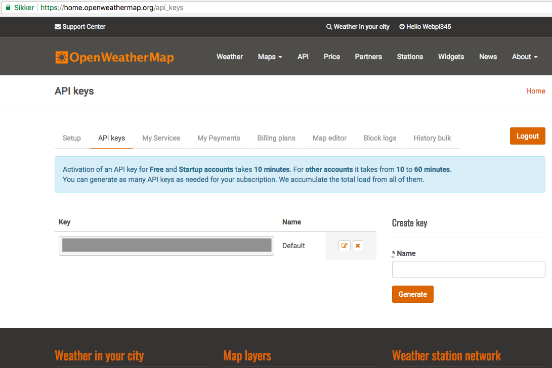
We get the weather data from OpenWeatherMap.org.
1. Start by making a FREE account on OpenWeatherMap.org.
2. Then copy your api-key to use later.
3. Now download and open the city.list.json file, and search for the cities you want displayed, and copy the city-id's for later.

Setting up the RPi with Oled
Make sure the RPi is connected to the internet
1. Enable the I2C and SPI function in raspi-config under Interfacing Options. Exit and reboot.
2. Run this to update:
sudo apt-get update3. Run the following commands to install the necessary libraries:
sudo apt-get install python-dev
#sudo python setup.py install
sudo apt-get install python-smbus
sudo apt-get install python-serial
sudo apt-get install python-imaging
4. Run the following command to open the configuration file:
sudo nano /etc/modulesMake sure the following two lines, are in the configuration file, then exit and reboot:
i2c-bcm2708
i2c-dev
5. Now run this to clone my github repo:
git clone https://github.com/Anders644PI/1.5inch-OLED-with-RPi.git
cd 1.5inch-OLED-with-RPi
6. Unzip wiringPi.zip:
unzip wiringPi.zip
cd wiringPi
And run these commands:
chmod 777 build
./build
Check the installation with:
gpio –v7. Go back to the main folder, by typing cd /home/pi/1.5inch-OLED-with-RPi/. Then unzip bcm2835-1_45.zip
unzip bcm2835-1_45.zip
cd bcm2835-1_45.zip
8. Then run this, to install the library:
./configure
make
sudo make check
sudo make install
9. Again go back to /home/pi/1.5inch-OLED-with-RPi/, and run this, to test the oled:
sudo python /Demo_Code/Python/main.py
Setting up the Pi with LEDs1
Source: https://tutorials-raspberrypi.com/connect-control-raspberry-pi-ws2812-rgb-led-strips/
1. We install the required packages (confirm with y):
sudo apt-get install gcc make build-essential python-dev git scons swig2. The audio output must be deactivated. For this we edit the file
sudo nano /etc/modprobe.d/snd-blacklist.confHere we add the following line:
blacklist snd_bcm28353. We also need to edit the configuration file:
sudo nano /boot/config.txt4. Now find this line:
# Enable audio (loads snd_bcm2835)
dtparam=audio=on
And comment it out.
# Enable audio (loads snd_bcm2835)
#dtparam=audio=on
5. Now reboot:
sudo rebootSetting up the Pi with LEDs2
1. Now we can download the library:
git clone https://github.com/jgarff/rpi_ws281x2. Run this:
cd rpi_ws281x/
sudo scons
3. And this:
cd python
sudo python setup.py build
sudo python setup.py install
4. Reboot and run the script:
sudo python /pi/home/1.5inch-OLED-with-RPi/OLED_driver_and_code_python/Temp-display-cities-led-after-button-ldr-next-v3.py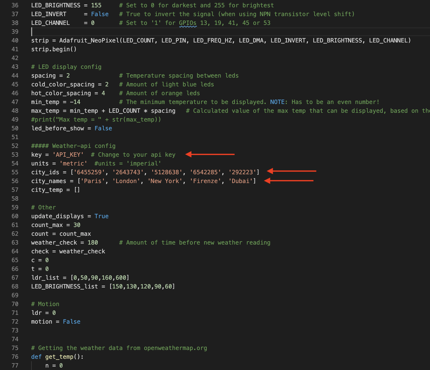
Configuring the Weather API
1. Cd into LED_Thermometer_Code_and_OLED_driver:
cd LED_Thermometer_Code_and_OLED_driver2. Then open Official_Digital_LED_Thermometer_v1-0.py:
nano Official_Digital_LED_Thermometer_v1-0.pyAnd then scroll down and edit the api-key, to your api key, from openweathermap.org, as shown in the image on the right.
Also change the city-ids and city names, to your desired locations.
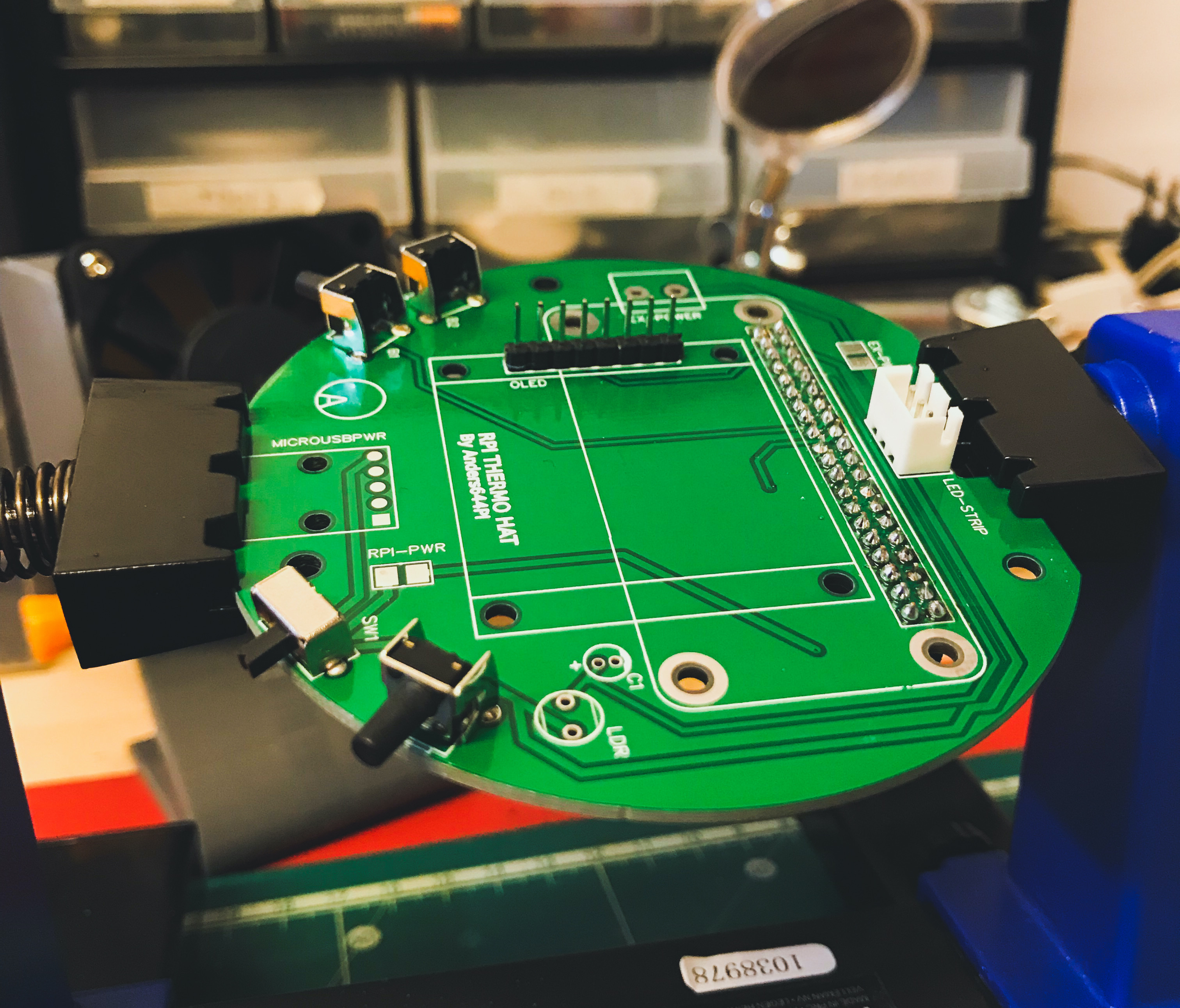
The Custom PCB
I then made a custom PCB, to solder all of the electronics onto.
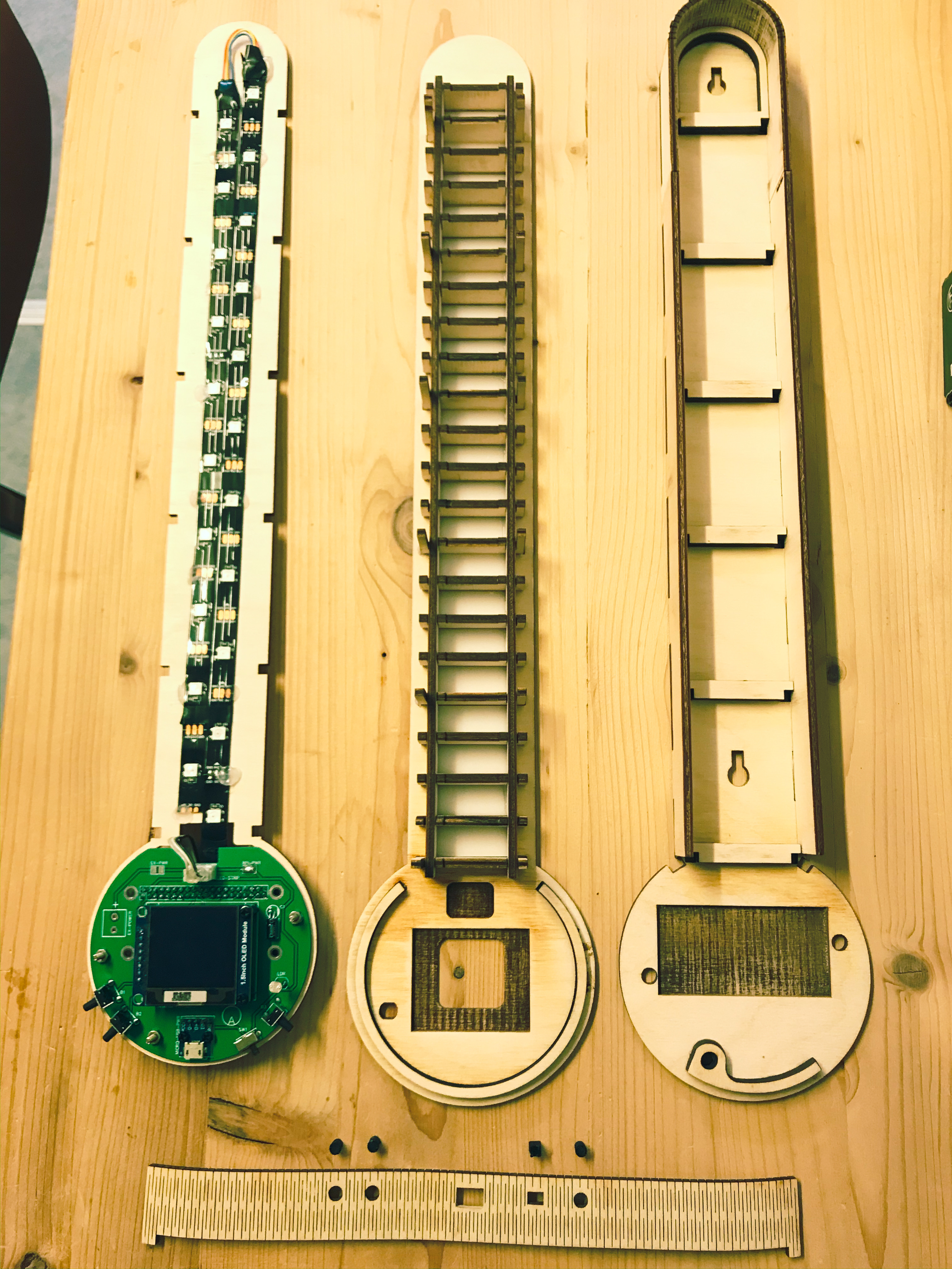
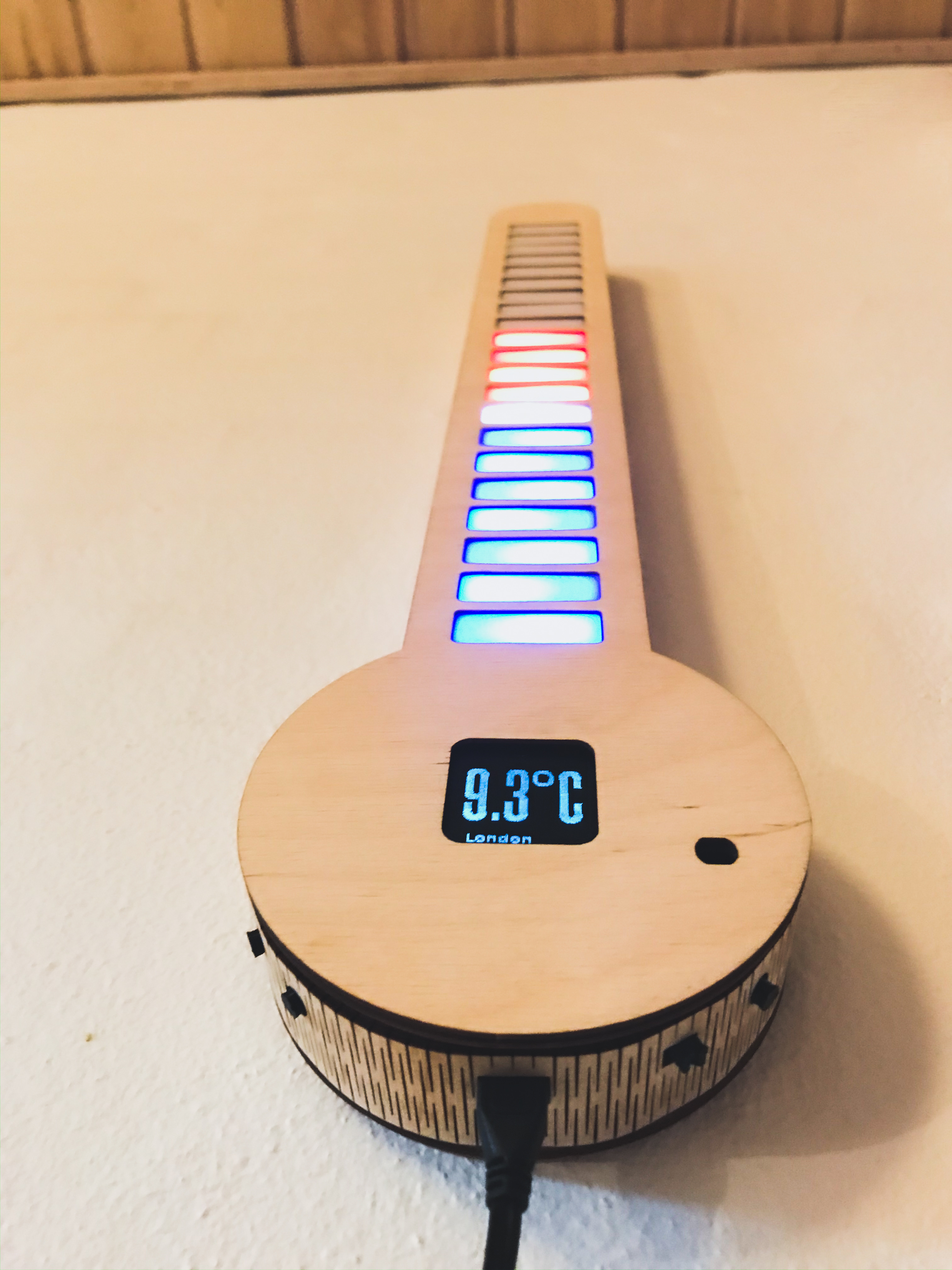
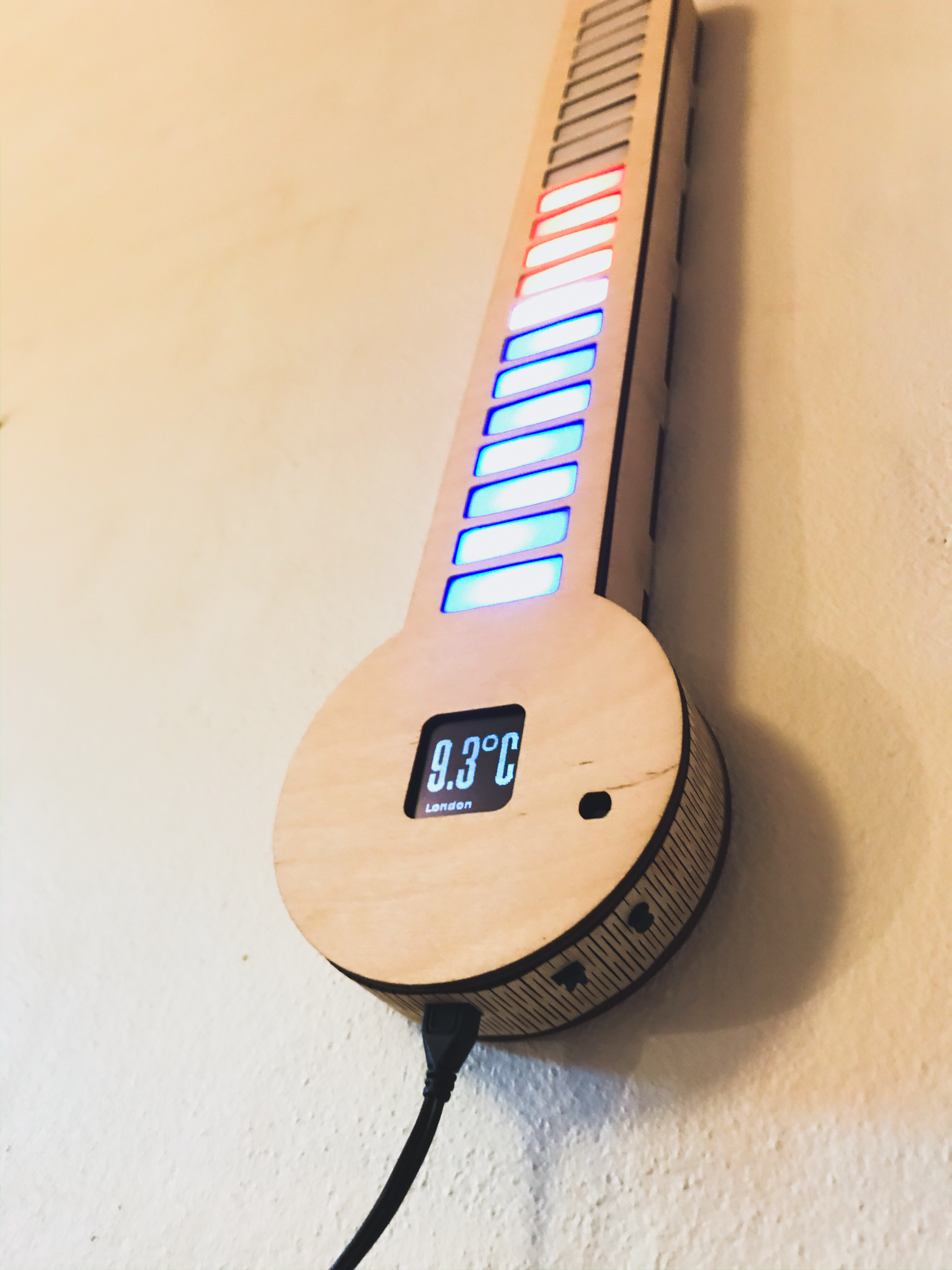
The Laser Cut Enclosure
Then I modeled an enclosure, and laser cut it out of 4mm and 6mm plywood. I also modeled in LED diffusers, which i cut out in 3mm acrylic.
After that I attached the electronics and the LED-strip to the laser cut plywood. And I then assembled the enclosure, partly with glue and friction.
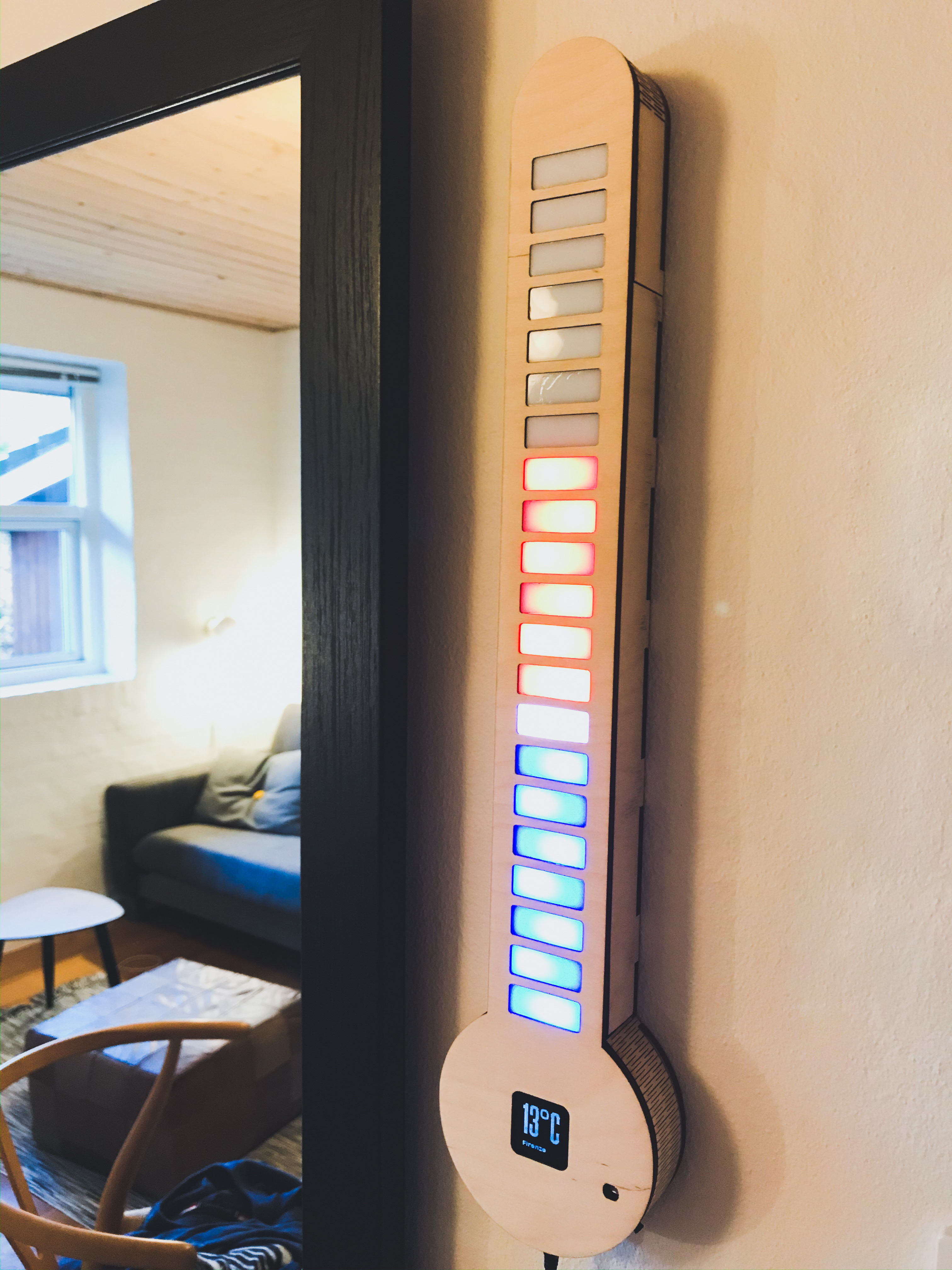
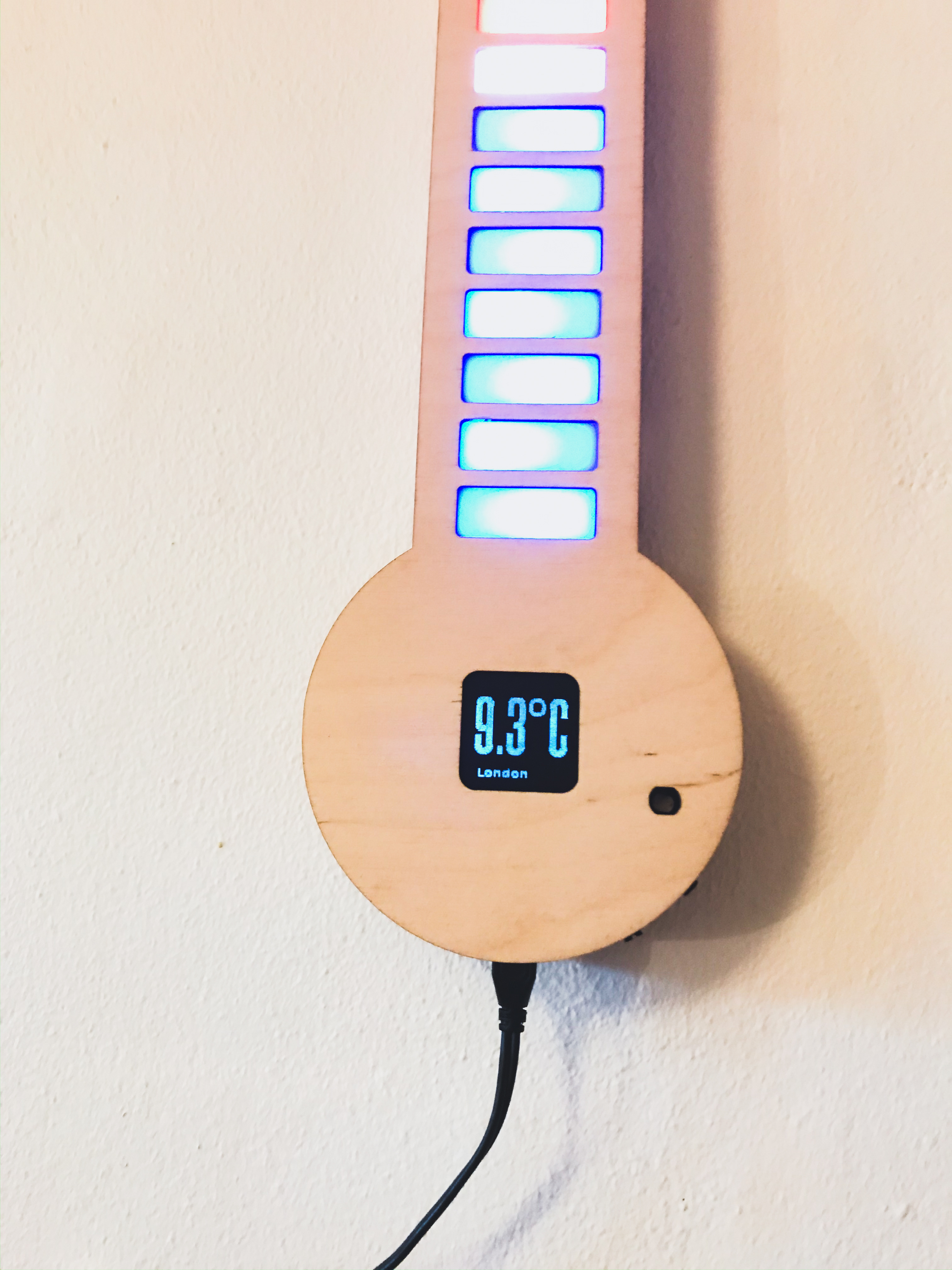
The result
So I hope you like my build.
If you are interested in buying the pcb with components, feel free to DM me, and we can arrange something. Note that i only have a limited supply.